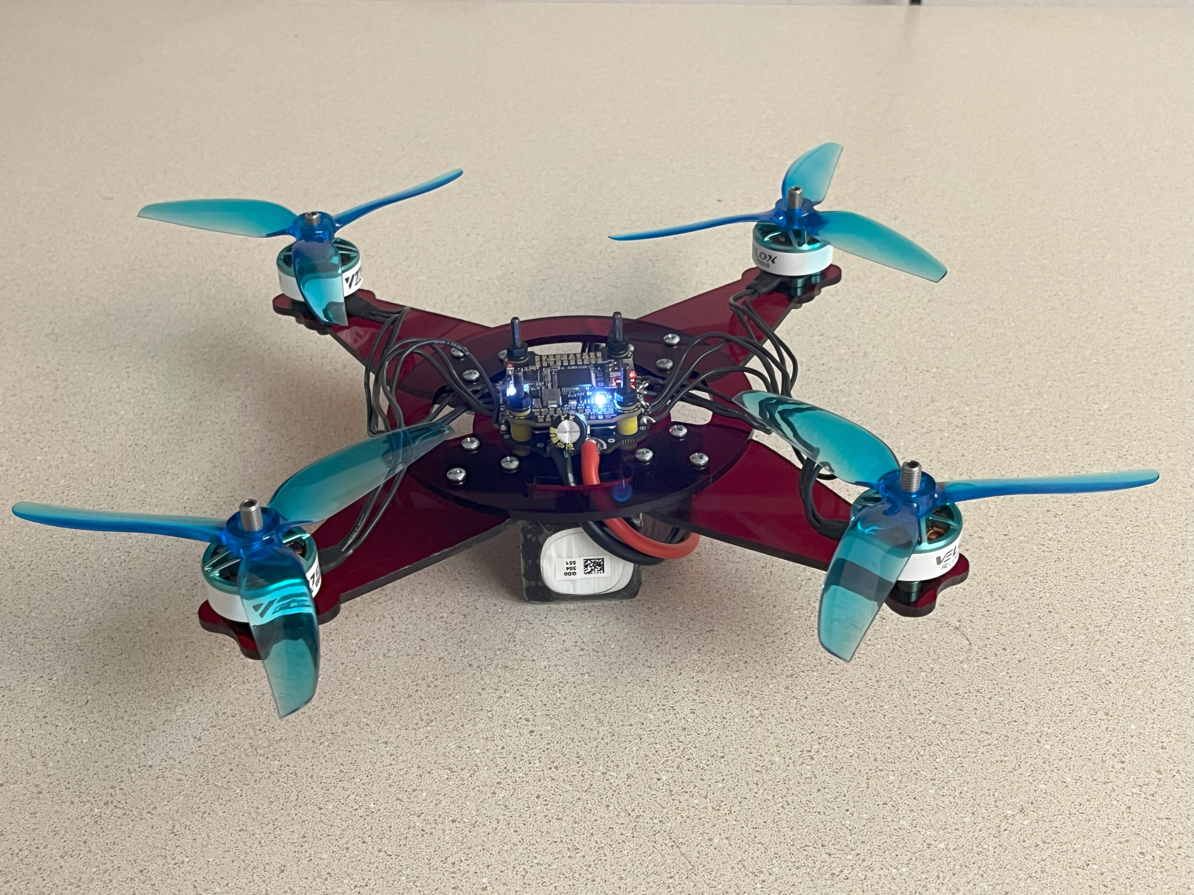
This build was born from an increasing fascination with drones, controls, and
maintaining flight with aerodynamically unstable bodies. The project was a practice
in modularity and optimization, needing a strong and firm, yet lightweight body that could be easily produced
and easily repaired. I started by researching the pros and cons of different
drone sizes, motors, batteries, and propellors, and settled on 5 inch propellers with 2207 1950KV motors
on a 4s battery for a balance of stability, ease of building, and flight time. (This is to say the motors
were 22mm diameter and 7mm height, with 1950 RPM per volt applied to the motor, and the battery is made from
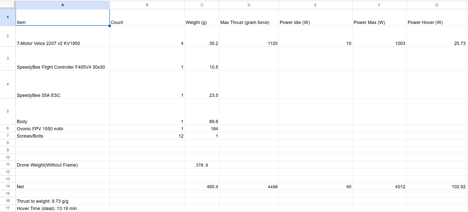
4 lipo cells, with a voltage of 4*3.7 = 14.8V). I created a spreadsheet to calculate
stats like net weight, max thrust, thrust to weight ratio, and flight time.
As it is, the motors draw around 10 watts each to hover, leading to an ideal flight time of
13 minutes on a 1500mAh 14.8V battery, though in practice this flight time is closer to 8 minutes under
normal loads.
When building the frame, I knew the maximum stress concentrations would occur in the arms, so I ran some simple cantilever beam stress equations to
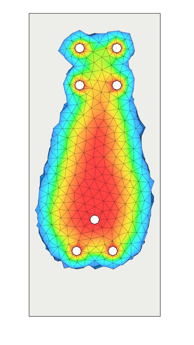
determine the strongest geometry for the arms. I then used finite element analysis and shape optimization based on a
rectangular arm with 4 forces at the motor mounts to create a
similarly optimized drone arm (which looked remarkably similar to my hand calculations), and built the rest of my drone frame in CAD.
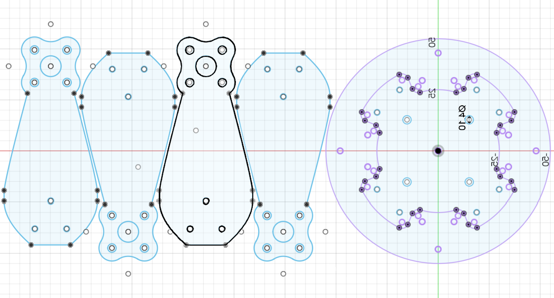
I realized at that having a top plate and bottom
plate cut separately would result in a large amount of wasted scrap material left on the plate acrylic, so I redesigned the 2 center parts of the frame to be built
out of concentric geometries rotated 45 degrees, which maintainted the same strenght while saving heavily on scrap. This design choice would allow for the frame to be
mass produced with minimal waste.
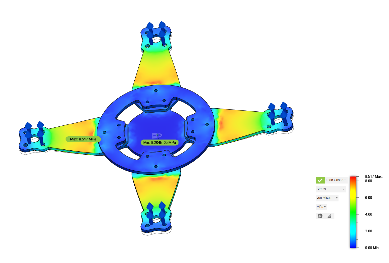
I then used further finite element analysis simulations to verify the strength of the drone, confirming that the arms would be hold the primary stress and strain
concentrations, with a stress factor of safety greater than 15x and a max deformation of 0.37 mm. However, a more important failure mode of the drone
is actually loss of control since motors top out at 4480 gram force, rough 44 newtons, far less than the maximum yield stress on any of the arms. As such,
vibrational analysis is very important, which is dependent primarily on the frequency of the motors and the natural frequency of the frame. (This is one of the reasons
that many frames are made of carbon fiber, the stiffness leads to much higher resonant frequencies far outside the range of motors). As such, I performed a FEA
frequency analysis and found the natural frequency of the frame was roughly 450 hz, while the motors top out at a theoretical ~480 hz. though this is a
theoretical max speed without load, the real top rpm would be slower, as such, I believed that my frame was sufficiently rigid to not suffer from feedback
vibrations from motors, which it did not.
After a little bit of test cuts to ensure that my screw holes were well dimensioned and the parts fit together well,
I assembled the frame with some common nuts and bolts, and soldered together my flight controller, ESC, and motors. (The flight controller is the main computer
of the drone, it makes all the minute calculations to balance power to each motor that keeps a drone from falling out of the air. It also
has sensors like gyroscopes, accelerometers, and altimeters to track its own movement. The ESC, or electronic speed controller is used to
turn a DC input voltage from the flight controller voltage into the necessary 3 phase AC power to run the brushless drone motor).
I hope to continue with this platform as a testing rig for testing my own drone control software.

